Lowering Rf Noise Floor With Cooling System

Box In Box Diagram Click To Enlarge Floating Floor Acoustic Floating

Underfloor Solar Heating Solar Solar Heating Solar Collector
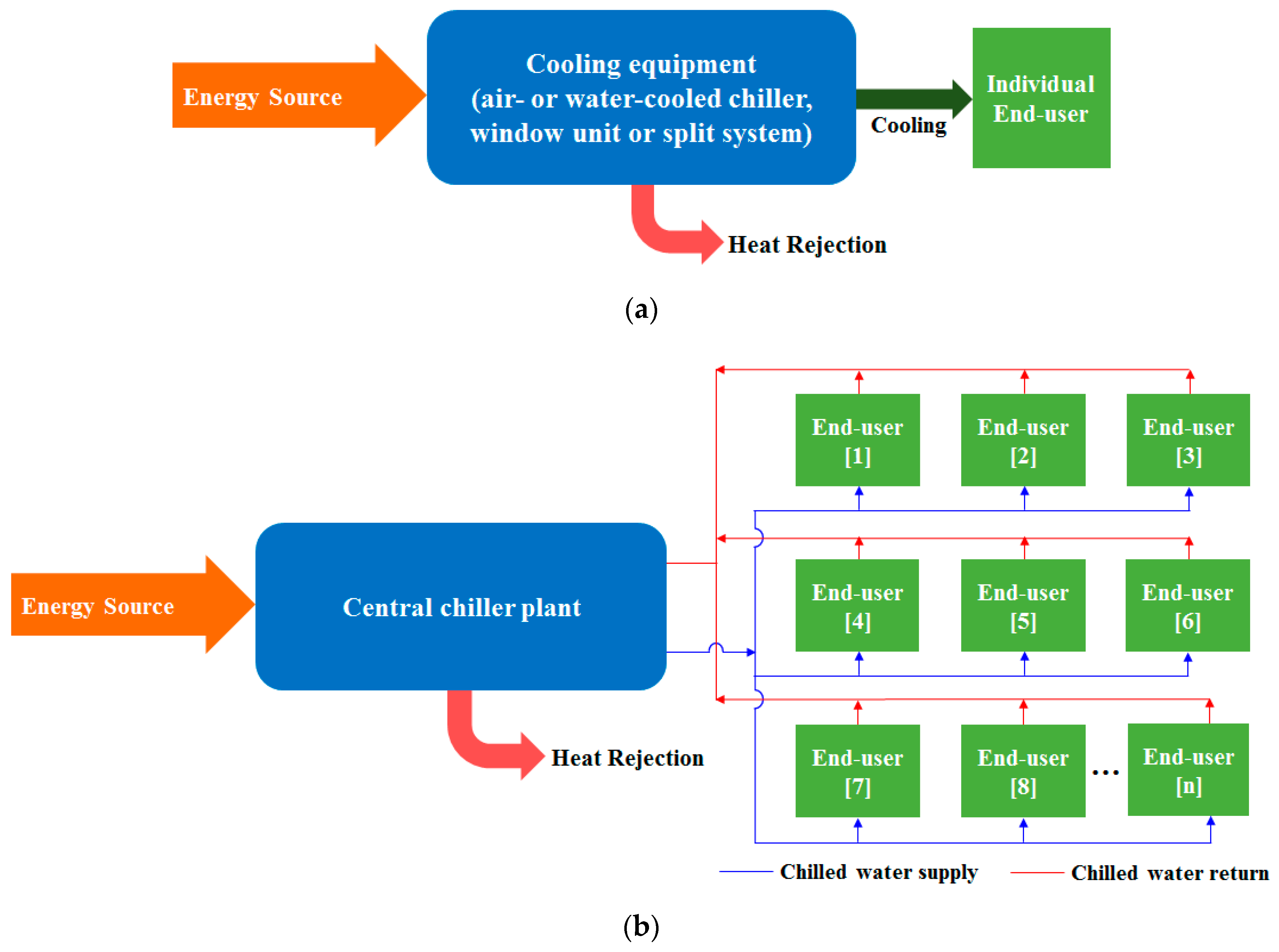
Energies Free Full Text Sustainable District Cooling Systems Status Challenges And Future Opportunities With Emphasis On Cooling Dominated Regions Html

Pin On Amateur Radio

What Is Immersion Cooling Liquid Immersion Cooling Submer

Engine Cooling An Overview Sciencedirect Topics

The amplifier also models a thermal noise floor so although this decrease is unrealistic it does not affect accuracy at the output stage.
Lowering rf noise floor with cooling system.

Pdf Thermal Comfort Under Radiant Asymmetries Of Floor Cooling System In 2 H And 8 H Exposure Durations

Pin By Hamsa Enviro Energy Solution On Solar Water Heating System Solar Water Heating System Water Heating Systems Solar Water Heating

Battery Cooling Advanced Thermal Solutions

Pdf Noise And Vibration Analysis For Automotive Radiator Cooling Fan

Product Impian Alseye Ram Cooler Pc Fan Ddr Memory Cooler With Du Ram Cooler Fan

Amd S Radeon R9 380x Graphics Card Reviewed Graphic Card Computer Accessories Amd

Apple Imac Aluminum Unibody 27 2009 In 2020 Imac Thin Body Digital Content

Pin On For The Home

Bohm B76 The Best Active Noise Cancelling Wireless Headphone Thetbpr Noise Cancelling Wireless Headphones Headphone

Dyson Fan Structure Mechanical Design Dyson Drone Design

Pin On Built Environment Tech Research 2019

Usb Mini Portable Air Conditioner Conditioning Humidifier Purifier Lig Koolgadgets Air Conditioning Fan Air Conditioner Air Cooler

Insul Tarp Insulation Used In A Radiant Heat Application Slab Insulation Insulation Pex Plumbing

Top 10 Best 120mm Rgb Fans In 2019 Reviews Led Case Led Computer Case

Premier Mobile Bluetooth Comfort Headset With Noise Canceling Mic In 2020 Noise Cancelling Mic Headset
Ni Pxi Chassis Design Advantages Ni

History Of Air Conditioning And Spot Cooling Infographic Infographic History A Heating And Air Conditioning Air Conditioner Repair Air Conditioning Repair

Unoisetion New Cavitation Technology Annoying Noise In Ears Caused By Cavitation Will Be Reduced 3 Times The C Ultrasonic Cavitation Slim Body Body Contouring

Hazardous Materials In E Waste Electronic Waste Recycling Process Plastic Components

Havit Hv F2056 15 6 17 Inch Laptop Cooler Cooling Pad Slim Portable Usb Powered 3 Fans Black Blue Laptop Cooling Pad Laptop Cooler Laptop Fan
What Is Generator Excitation System And Its Main Role Generation Electrical Projects Regulators

Uml 2 Component Diagrams An Agile Introduction Software Architecture Diagram Thermostat Diagram Architecture

Radiant Heat In 2020 Radiant Heat Floor Heating Systems Home Greenhouse

The Latest Products In Solar Power Floor Heating Systems Radiant Floor Heating Hydronic Radiant Floor Heating
Source : pinterest.com
